Reversible Computing#
In the previous chapter, we introduced the concept of Boolean operators such as the binary operations AND and OR. A critical aspect of these elements is that they are not reversible. In other words, we cannot figure out the value of their inputs based solely on the value of their output.
In case this is not entirely obvious, let’s look again at the truth table for the AND operation:
\(b\) |
\(a\) |
\(b \land a\) |
|---|---|---|
\(0\) |
\(0\) |
\(0\) |
\(0\) |
\(1\) |
\(0\) |
\(1\) |
\(0\) |
\(0\) |
\(1\) |
\(1\) |
\(1\) |
Here we can see that if our output is \(1\), we can confidently affirm that our inputs are \(b = 1\) and \(a = 1\). However, if the output is \(0\), it is not possible to predict with certainty what the values of \(a\) and \(b\) are. This uncertainty is equivalent to a loss of information in our system.
Reversible computing was born from the idea that the loss of information in classical Boolean circuits is associated with power dissipation [Landauer61]. In an effort to find more power-efficient ways to implement circuits, a model of reversible computation emerged [Bennett73], and with it, a corresponding set of logical gate abstractions to perform these computations [Toffoli80, Fredkin81]\(^*\).
It was very quickly realized that a model of computation at the quantum-mechanical level can be developed following these same rules [Benioff79, Feynman85], and expanded to include non-classical operations such as superposition and entanglement [Deutsch85, Peres85, Deutsch88, Margolus89]. Therefore, understanding the basic principles of reversible computing is an important step towards a model of quantum computation.
1. Reversible Logic#
We begin by analyzing the basic operations we reviewed in the previous chapter in an effort to make them reversible.
1.1 Reversible NOT#
The first thing to note is that the NOT gate is reversible. This because we can confidently predict the input value directly from its output. If the output is \(1\), we know for a fact the input was \(0\), and vice versa. Furthermore, we can reverse the computation of a NOT gate by applying another NOT right after.
Now, because the symbol for the logic NOT gate is not symmetric, Feynman suggested changing it to simply using an X over a wire. However, from now on, we will instead use the symbol commonly utilized in quantum computing circuits, which is an X inside a box\(^{\dagger}\):

For this same reason, we will now refer to the NOT gate as the \(\text{X}\) gate.
1.2 Reversible XOR#
The reversible version of the XOR gate is perhaps the most fundamental 2-bit operation in reversible computing, and one of the most widely used gates in quantum circuits. We can implement this operation by the used of a what is known as a controlled-\(\text{X}\) or \(\text{CX}\) gate. A \(\text{CX}\) gate has a control line and a target line. The value on the control line determines if an \(\text{X}\) gate on the target line gets applied or not:
If the control line is \(0\), the target line is left unchanged.
If the control is \(1\), the \(\text{X}\) gate is activated, inverting the value of target line.
The figure below shows the schematic representation of a \(\text{CX}\) gate where the top line is the control, and the bottom line is the target:
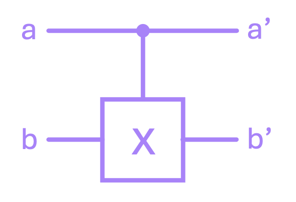
Following this logic, we can make a truth table for what the outputs \(a'\) and \(b'\) look like with respect to the inputs \(a\) and \(b\), which clearly shows that \(a' = a\), and more importantly, \(b' = a \oplus b\):
\(a\) |
\(b\) |
\(a'\) |
\(b'\) |
|---|---|---|---|
\(0\) |
\(0\) |
\(0\) |
\(0\) |
\(0\) |
\(1\) |
\(0\) |
\(1\) |
\(1\) |
\(0\) |
\(1\) |
\(1\) |
\(1\) |
\(1\) |
\(1\) |
\(0\) |
The output \(b'\) is the same as what we would get with a classical XOR gate, but the simple fact of carrying the input \(a\) to the output \(a'\) allows us to be able to always predict the value of both inputs (\(a\) and \(b\)) directly from the outputs (\(a'\) and \(b'\)). This should be clear from the fact that for each possible input there is only a single unique possible output.
Furthermore, the operation of a \(\text{CX}\) gate can be uncomputed (reversed) by applying another \(\text{CX}\) right after! We can verify this with a few lines of code. Let’s first implement a \(\text{CX}\) gate and generate its truth table in Python:
# define x gate as a function:
def x(a_in):
    a_out = a_in ^ 1   # Remember ^ performs the XOR operation. a^1 = a̅
    return a_out
# define cx gate as a function:
def cx(a_in, b_in):

    # a' is always equal to a.
    a_out = a_in

    # if control is one (i.e., a == 1): negate target (b' = b̅),
    # else: leave b alone (b' = b).
    if a_in == 1:
        b_out = x(b_in)
    else:
        b_out = b_in

    return (a_out, b_out)
# Print table for CX gate
print('CX gate:')
print('a | b || a\' | b\' |')

# Iterate over possible combinations of a and b
for a, b in [(0,0), (0,1), (1,0), (1,1)]:
    ap, bp = cx(a,b)
    print(f'{a} | {b} || {ap}  | {bp}  |')
CX gate:
a | b || a' | b' |
0 | 0 || 0  | 0  |
0 | 1 || 0  | 1  |
1 | 0 || 1  | 1  |
1 | 1 || 1  | 0  |
We can see that \(a' = a\) and \(b' = a \oplus b\), so our \(\text{CX}\) function seems to be working correctly. Let’s now apply it twice:
# Print table for applying two CX gates
print('Two CX gates:')
print('a | b || a\'\' | b\'\' |')

# Apply CX twice for all combination of inputs a, b.
for a, b in [(0,0), (0,1), (1,0), (1,1)]:
    ai, bi = cx(a,b)
    ap, bp = cx(ai,bi)
    print(f'{a} | {b} || {ap}   | {bp}   |')
Two CX gates:
a | b || a'' | b'' |
0 | 0 || 0   | 0   |
0 | 1 || 0   | 1   |
1 | 0 || 1   | 0   |
1 | 1 || 1   | 1   |
It is clear that, after applying to \(\text{CX}\) gates in a row, the inputs \(a\) and \(b\) now match the ouputs \(a''\) and \(b''\), which means the computation has been reversed.
1.2 Reversible COPY#
A reversible implementation of the COPY or FANOUT operation can be easily implemented by simply taking a \(\text{CX}\) and always setting the input of the target line to \(0\):
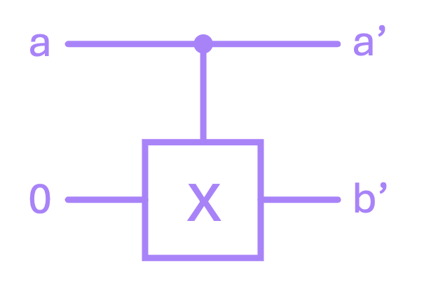
We can see from the \(\text{CX}\) truth table that if \(b = 0\), then \(b' = a' = a\).
1.3 Reversible AND#
Recall that for an AND gate, three of the four possible outputs are equal to \(0\):
\(a\) |
\(b\) |
\(a \land b\) |
|---|---|---|
\(0\) |
\(0\) |
\(0\) |
\(0\) |
\(1\) |
\(0\) |
\(1\) |
\(0\) |
\(0\) |
\(1\) |
\(1\) |
\(1\) |
This poses a challenge because it is then not possible to predict both of the input values using just the output (\(a \land b\)) and only one of the inputs (\(a\) or \(b\)). The consequence of this is that we need a 3-bit gate in order to construct a reversible AND operation. The way to do this is by the use of a controlled-controlled-X or \(\text{CCX}\) gate, also often referred as a Toffoli gate.
The \(\text{CCX}\) gate operates in a similar fashion to the \(\text{CX}\) gate, except that we now have two control lines and one target line, where an \(\text{X}\) gate is apply iff both of the control lines are equal to \(1\):
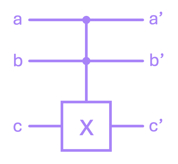
Using this condition, the truth table for the \(\text{CCX}\) is given by:
\(a\) |
\(b\) |
\(c\) |
\(a'\) |
\(b'\) |
\(c'\) |
|---|---|---|---|---|---|
\(0\) |
\(0\) |
\(0\) |
\(0\) |
\(0\) |
\(0\) |
\(0\) |
\(0\) |
\(1\) |
\(0\) |
\(0\) |
\(1\) |
\(0\) |
\(1\) |
\(0\) |
\(0\) |
\(1\) |
\(0\) |
\(0\) |
\(1\) |
\(1\) |
\(0\) |
\(1\) |
\(1\) |
\(1\) |
\(0\) |
\(0\) |
\(1\) |
\(0\) |
\(0\) |
\(1\) |
\(0\) |
\(1\) |
\(1\) |
\(0\) |
\(1\) |
\(1\) |
\(1\) |
\(0\) |
\(1\) |
\(1\) |
\(1\) |
\(1\) |
\(1\) |
\(1\) |
\(1\) |
\(1\) |
\(0\) |
Even though there are a lot of numbers in this table, the results are simple. the outputs \(a'\) and \(b'\) are always equal to the inputs \(a\) and \(b\), respectively. And the output \(c'\) is equal to the input \(c\) unless \(a = b = 1\), in which case \(c' = \bar{c}\).
Now, for the specific case in which we set the input \(c\) always equal to \(0\), we get expected behavior for an AND gate where \(c' = (a \land b)\):
\(a\) |
\(b\) |
\(c\) |
\(a'\) |
\(b'\) |
\(c'\) |
|---|---|---|---|---|---|
\(0\) |
\(0\) |
\(0\) |
\(0\) |
\(0\) |
\(0\) |
\(0\) |
\(1\) |
\(0\) |
\(0\) |
\(1\) |
\(0\) |
\(1\) |
\(0\) |
\(0\) |
\(1\) |
\(0\) |
\(0\) |
\(1\) |
\(1\) |
\(0\) |
\(1\) |
\(1\) |
\(1\) |
It is also worth noting that, if we were to set \(c = 1\) instead, then we get the response of a NAND gate: \(c' = (\overline{a \land b})\).
And once again, just like with the \(\text{CX}\) gate, the \(\text{CCX}\) gate is reversible. Let’s verify this in Python by first creating a \(\text{CCX}\) and then applying it twice:
# define ccx gate as a function:
def ccx(a_in, b_in, c_in):

    # a' and b' are always equal to a and b.
    a_out = a_in
    b_out = b_in

    # if both controls are 1: negate target (c' = c̅), else: leave b alone (c' = c).
    if a_in == 1 and b_in == 1:
        c_out = x(c_in)
    else:
        c_out = c_in

    return (a_out, b_out, c_out)
# Print table for CCX gate when input c is zero
print('CCX gate (with c = 0):')
print('a | b | c || a\' | b\' | c\' |')

# Iterate over possible combinations of a and b (c is always 0)
for a, b in [(0,0), (0,1), (1,0), (1,1)]:
    ap, bp, cp = ccx(a,b,0)
    print(f'{a} | {b} | 0 || {ap}  | {bp}  | {cp}  |')
CCX gate (with c = 0):
a | b | c || a' | b' | c' |
0 | 0 | 0 || 0  | 0  | 0  |
0 | 1 | 0 || 0  | 1  | 0  |
1 | 0 | 0 || 1  | 0  | 0  |
1 | 1 | 0 || 1  | 1  | 1  |
As expected, we see that \(a' = a\), \(b' = b\) and \(c' = a \land b\). Let’s now apply the \(\text{CCX}\) twice and verify we can reverse the computation by checking all outputs match out original inputs:
# Print table for applying two CCX gates when input c is zero
print('Two CCX gates (with c = 0):')
print('a | b | c || a\'\' | b\'\' | c\'\' |')

# Apply CX twice for all combination of inputs a, b.
for a, b in [(0,0), (0,1), (1,0), (1,1)]:
    ai, bi, ci = ccx(a,b,0)
    ap, bp, cp = ccx(a,b,ci)
    print(f'{a} | {b} | 0 || {ap}   | {bp}   | {cp}   |')
Two CCX gates (with c = 0):
a | b | c || a'' | b'' | c'' |
0 | 0 | 0 || 0   | 0   | 0   |
0 | 1 | 0 || 0   | 1   | 0   |
1 | 0 | 0 || 1   | 0   | 0   |
1 | 1 | 0 || 1   | 1   | 0   |
An important aspect to keep in mind is that the \(\text{CCX}\) gate (not the AND gate) is the one that’s reversible. The AND implementation is just a special case where we set one of its inputs to be a constant value, but we can do the same exercise for when \(c\) can take an arbitrary value.
1.4 Reversible OR#
To implement a reversible OR gate, we can use the following Boolean algebra identity:
This expression basically says that we can implement an OR gate if we negate both of the inputs to an NAND gate:

So, for the reversible case of an OR, we can use two \(\text{CCX}\) gates to negate the inputs \(a\) and \(b\), and use a \(\text{CCX}\) gate with \(c = 1\) as our NAND gate:
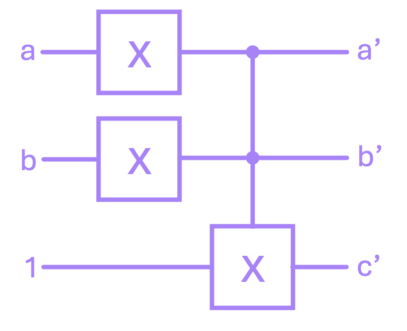
Now, to show the reversibility of this composite gate, we might be tempted to think that, just like with the previous examples, applying it twice will reverse the operation (which actually gives the right answer in this particular case). However, what we want to do to “uncompute” the result is use the inverse of our circuit. In other words, we want to apply each of the gates in the reverse order:
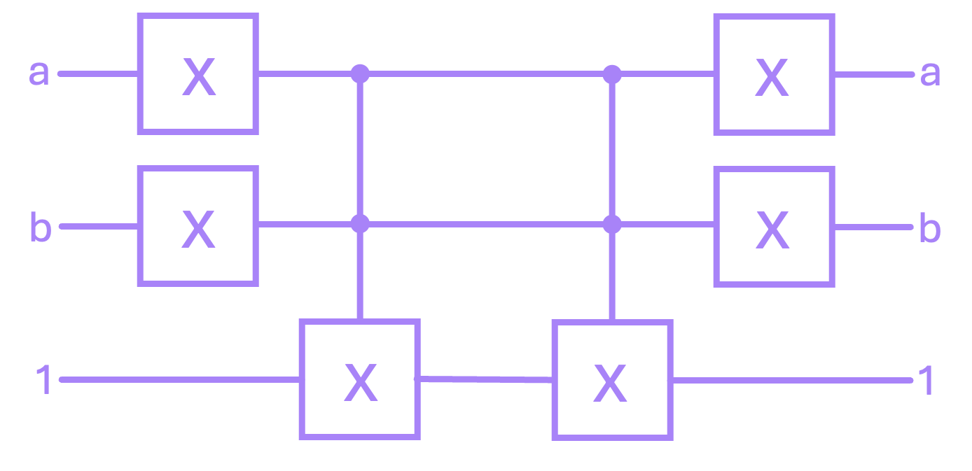
It is worth highlighting that, when we switch from working with classical circuits to quantum circuits, we will still need to apply our gates in reverse to invert a result. However, because in some cases we will be dealing with complex numbers, there will be an additional requirement to perform this uncomputation for certain gates, but we do not need to worry about this condition quite yet.
To check the reversibility of the circuit above, we can first check the results for the OR gate by using the \(\text{CX}\) and \(\text{CCX}\) we defined above:
# Print table for a reversible OR gate
print('Reversible OR:')
print('a | b | c || a\' | b\' | c\' |')

# Iterate over possible combinations of a and b (c is always 1)
for a, b in [(0,0), (0,1), (1,0), (1,1)]:
    an = x(a)
    bn = x(b)
    ap, bp, cp = ccx(an,bn,1)
    print(f'{a} | {b} | 1 || {ap}  | {bp}  | {cp}  |')
Reversible OR:
a | b | c || a' | b' | c' |
0 | 0 | 1 || 1  | 1  | 0  |
0 | 1 | 1 || 1  | 0  | 1  |
1 | 0 | 1 || 0  | 1  | 1  |
1 | 1 | 1 || 0  | 0  | 1  |
The results above match out expectation of having \(c' = a \lor b\). Let’s now apply the OR gate followed by their corresponding gates in reverse:
# Print table for applying an reversible OR gate followed by its inverse
print('Apply OR, then apply all gates in reverse:')
print('a | b | c || a\'\' | b\'\' | c\'\' |')

# Iterate over possible combinations of a and b (c is always 1)
for a, b in [(0,0), (0,1), (1,0), (1,1)]:
    an = x(a)
    bn = x(b)
    ai, bi, ci = ccx(an,bn,1)
    ap, bp, cp = ccx(ai,bi,ci)
    app = x(ap)
    bpp = x(bp)
    cpp = cp

    print(f'{a} | {b} | 1 || {app}   | {bpp}   | {cpp}   |')
Apply OR, then apply all gates in reverse:
a | b | c || a'' | b'' | c'' |
0 | 0 | 1 || 0   | 0   | 1   |
0 | 1 | 1 || 0   | 1   | 1   |
1 | 0 | 1 || 1   | 0   | 1   |
1 | 1 | 1 || 1   | 1   | 1   |
2. Reversible Circuits#
In the previous section, we constructed a reversible OR gate by using other gates: two \(\text{X}\) gates and a \(\text{CCX}\) gate. We can use this same idea to compose more complex circuits. And, since we have now shown that we have the basic gates we had for non-reversible logic, we should be able to basically implement any circuit we want.
For example, we could construct a one-to-one replacement of the full adder we showed in the previous chapter:
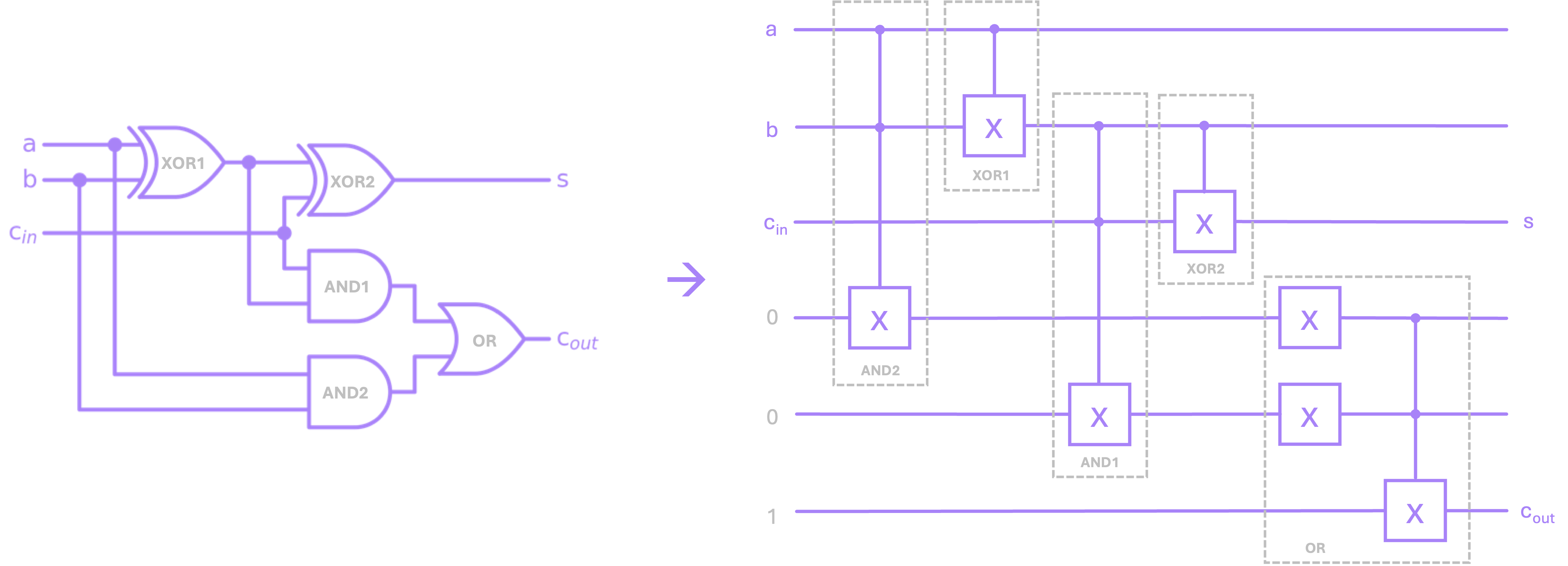
One thing to note about the reversible version of this circuit is that, it will be fairly common to require several “auxiliary” lines to carry out our computation and provide a result. In this particular example, we managed to get the sum output \(s\) using only the lines connected to our inputs, but to compute the output carry \(c_{out}\) we needed three additional lines initialized to some specific value.
Lastly, just to verify that the circuit above does indeed act as a full adder, we can use the \(\text{X}\), \(\text{CX}\) and \(\text{CCX}\) Python functions we defined above to implement this circuit. We will only display the relevant outputs \(s\) and \(c_{out}\), but the code makes all five outputs available in case we wanted to reverse the computation.
# Print table for a reversible Full Adder
print('Reversible Full Adder')
print(f'a | b | cin || s | cout |')

# Iterate over possible combinations of a, b and cin
inputs = [(0,0,0), (0,0,1), (0,1,0), (0,1,1),
          (1,0,0), (1,0,1), (1,1,0), (1,1,1)]

for a, b, c in inputs:
    a1, b1, d1 = ccx(a, b, 0)      # AND1
    a2, b2 = cx(a1, b1)            # XOR1
    a3, c3, e3 = ccx(b2, c, 0)     # AND2
    b4, s = cx(b2, c3)             # XOR2

    d5 = x(d1)                     # OR ...
    e5 = x(e3)                     #
    d6, e6, cout = ccx(d5, e5, 1)  #

    print(f'{a} | {b} | {c}   || {s} | {cout}    |')
Reversible Full Adder
a | b | cin || s | cout |
0 | 0 | 0   || 0 | 0    |
0 | 0 | 1   || 1 | 0    |
0 | 1 | 0   || 1 | 0    |
0 | 1 | 1   || 0 | 1    |
1 | 0 | 0   || 1 | 0    |
1 | 0 | 1   || 0 | 1    |
1 | 1 | 0   || 0 | 1    |
1 | 1 | 1   || 1 | 1    |
As expected, the output above matches the truth table for a full adder we showed in the previous chapter. If we wanted to “uncompute” these results, we will then apply each an every gate in our circuit but in reverse order.
Now, as our circuits grow in complexity, keeping track of line using truth tables becomes rather complicated. However, a very nice property of reversible circuits is that, their input-to-output response can be perfectly mapped onto a matrix. Therefore, we can use linear algebra to perform all of our computations.
Understanding this mapping is a core principle in quantum computing, so we will dedicate the next chapter to explain how this is done.
Footnotes#
\(^*\)Even though Fredkin’s paper was published in 1981, this work is referenced in Toffoli’s 1980 paper as “unpublished notes from Prof. Fredkin’s lectures collected and organized by Bill Silver” with 1978 as the publication year. (go back)
\(^{\dagger}\)The fact that Feynman used an X to denote the circuit diagram for a reversible NOT gate is merely coincidental with the notion of using an X as the symbol for its corresponding quantum gate. The reason why we call the quantum NOT an \(\text{X}\) gate has to do with its relationship with the Pauli-X matrix (a topic that we will cover in detail in a later chapter). (go back)